3×0.75 mm² + 2SMF Double-Sheath Zero-Buoyancy Optoelectric Cable, 11.8 mm
Zero-Buoyancy Cables · Marine & Subsea
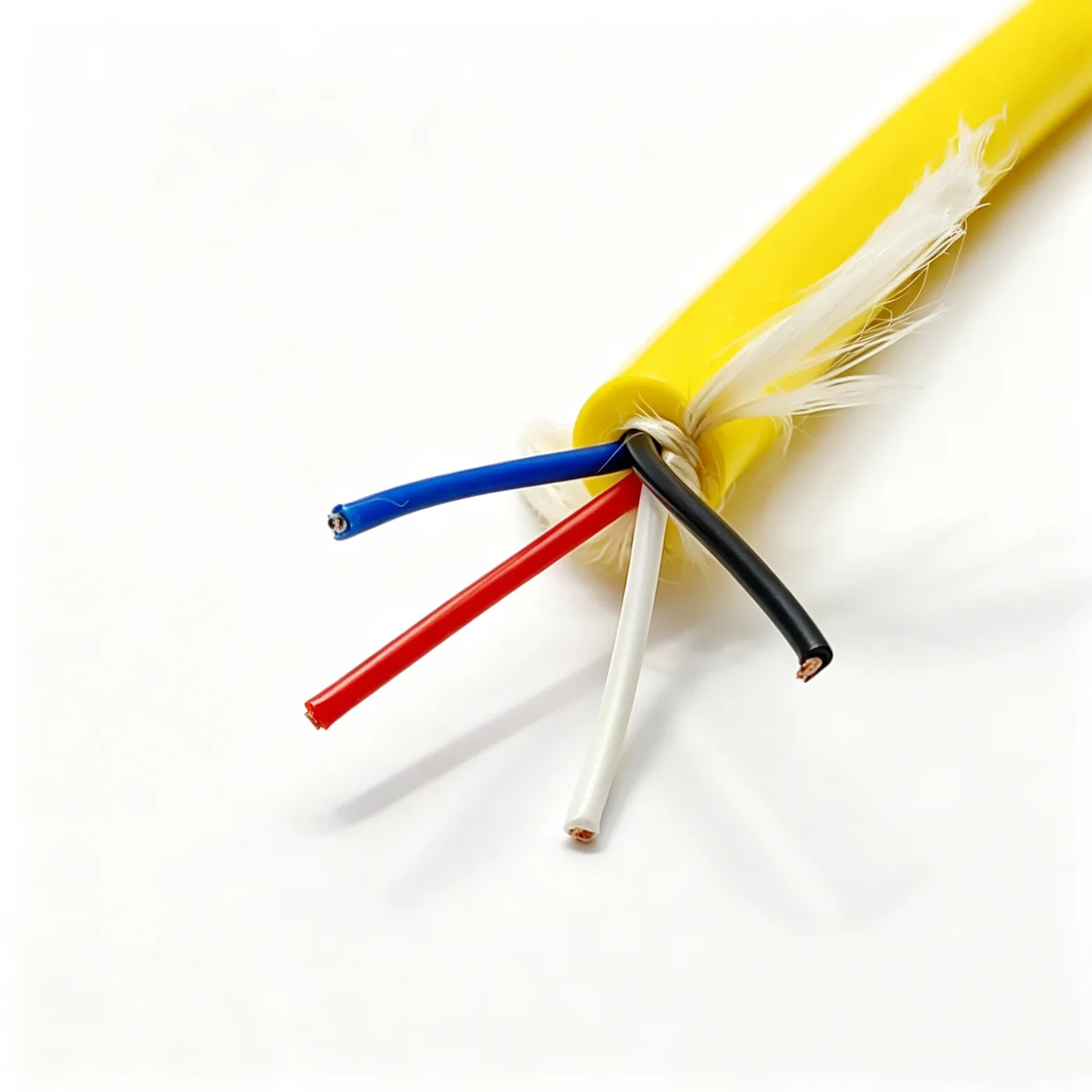
Double-sheath buoyant cable 3×0.75+2SMF
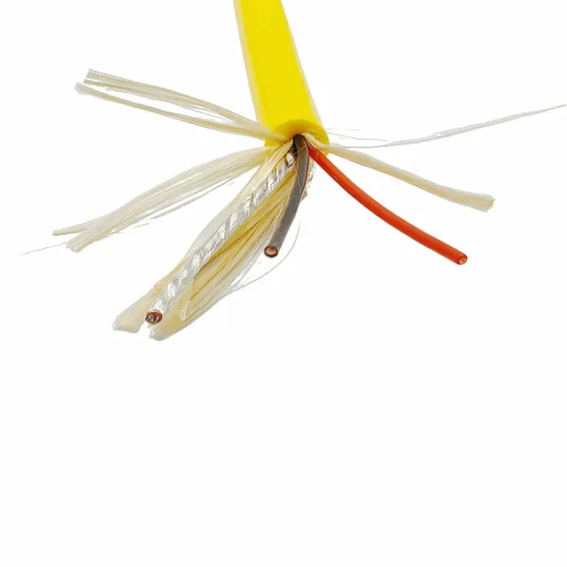
Double-sheath buoyant optoelectric cable with 3×0.75 mm² power cores and two single-mode fibres, foamed TPU buoyancy layer, 11.8 mm finished OD.
Product overview
Zero-buoyancy cables are used for underwater power and signal transmission. Their design aim is neither to float nor to sink noticeably in water, so that the cable imposes as little additional load as possible on the underwater equipment. For underwater robots, sonar tow bodies and underwater camera and survey systems, the buoyancy characteristics of the cable directly affect attitude control, endurance and handling, so such cables usually have to combine low density, water pressure resistance, hydrolysis resistance and flexibility for easy deployment.
This double-sheath buoyant cable from PAIDE Cable uses an optoelectric composite construction, integrating three power cores and two single-mode fibres in one cable body, so that a single line carries power, control and data return and the number of external harnesses and the risk of tangling are reduced. From the inside out the cable comprises cores, cabling layer, foamed buoyancy layer and outer sheath, with each layer clearly defined in function so that it can be adapted to working depth and environment.
Construction and materials
- Conductor: bare copper, 0.75 mm² multi-strand stranded, stranded diameter 1.12 mm, tightly stranded so that it does not loosen under repeated bending
- Insulation: PE, 0.5 mm thick, insulation diameter 2.1 mm, the three cores in black, red and white for easy identification at both ends
- Fibre unit: two single-mode fibres laid with the cable, carrying signal and data return independently of the power cores without mutual interference
- Cabling: power cores and fibre unit stranded together in the same direction, cabling diameter 5±0.2 mm, giving a round core with even stress between layers
- Fillers and separation: 7 × 3000D LCP fibres run along the core and also carry longitudinal tension, with a non-woven tape wrap outside as separation
- Inner sheath: foamed TPU, 2.9 mm thick, formed into a low-density layer by foaming, which is the main source of buoyancy in the cable
- Outer sheath: TPU, thin-wall extruded, yellow, applied over the foamed layer to provide sealing, abrasion resistance and hydrolysis resistance
- Finished outer diameter: 11.8±0.3 mm, a compact cross-section with overall density close to that of water
Bare copper is chosen for the conductor to obtain stable conductivity within the weight allowance of underwater equipment; the multi-strand construction makes the cable easier to bend during deployment and spooling and reduces fatigue damage to the copper wires from repeated flexing. PE is chosen for the insulation because its dielectric performance is stable and its water absorption low, so that insulation resistance is maintained after long immersion, while giving the cores a regular shape for subsequent cabling.
The fibre unit and the power cores are cabled separately, so that the optical channel does not depend on the copper conductors, power and communication each follow their own path, and immunity to electromagnetic interference is better; LCP fibre fills the core and also acts as a strength member, leaving the tensile load to the fibre so that the copper conductor only conducts and is not drawn down or broken when the cable is loaded.
Buoyancy comes from the foamed inner sheath: the foamed layer reduces density while maintaining strength, bringing the cable close to neutral in water. The outer sheath is thin-wall extruded both to keep weight under control and to give the foamed layer a dense closed surface that blocks water and oil ingress, keeping the foam structure stable under long immersion.
Key characteristics
- Near-zero buoyancy: very low weight in water, so deployment does not pull the equipment noticeably down or up
- Integrated power and fibre: power and optical signals over one cable, reducing harness count and joint stages
- Separate load-bearing: strength fibres and copper conductors are arranged separately, so tension does not act directly on the conductive cores
- Double sheath: the foamed layer provides buoyancy and the outer sheath provides sealing and abrasion protection, each layer serving its own purpose
- Soft and easy to deploy: stranded conductors with a loose cabling lay give a supple cable suited to spooling and repeated deployment
- Environmental resistance: the sheath material resists hydrolysis, oil and salt spray, suiting long-term underwater and damp conditions
Electrical and mechanical performance
The rated voltage, continuous operating temperature, minimum bending radius, permissible tension and DC resistance of this product vary with working depth, deployment method and connector type. They are therefore not fixed on this page and are subject to the specification document confirmed by both parties; the installation and pulling method should be determined only after checking the selected specification.
Where required, tests such as continuity, insulation resistance, withstand voltage, fibre attenuation and dimensional checks can be arranged to project requirements, with the test methods and acceptance criteria likewise subject to the confirmed specification. During installation and use, small-radius hard bends, sharp-edge abrasion and excessive pulling should be avoided, joints should be sealed against water, and mud and salt should be cleaned from the cable surface after deployment.
Typical applications
- Combined power and signal transmission for underwater robots and underwater work platforms
- Tow cables for sonar tow bodies and underwater survey equipment
- Power and data return for underwater camera, lighting and inspection equipment
- Deployment of ocean observation, hydrographic survey and sampling equipment
- Temporary cables for underwater structural inspection, salvage and repair work
In these applications the neutral buoyancy of the cable reduces its effect on equipment attitude, while the optoelectric construction lets the equipment complete power supply and communication over a single cable, simplifying connection and deployment preparation before work; where equipment is deployed and recovered repeatedly, flexibility and sheath abrasion resistance directly determine cable service life.
Selection and customisation notes
Core count and conductor cross-section, fibre count and fibre type, cabling lay and sheath thickness can all be adjusted to project requirements; if the equipment imposes stricter limits on weight and buoyancy balance, the thickness of the foamed layer can be adjusted so that the cable behaves closer to the user's expectations in water.
Outer sheath colour, finished length, end connector type and breakout arrangement can also be customised; length and connector solutions should be defined after matching the equipment interface, deployment gear and guide sheaves. For greater depths or long-term immersion, state the working depth, medium and deployment frequency at the selection stage so that sheath material and layer structure can be determined.
Where the cable is to be matched to existing equipment, the interface dimensions, permissible outer diameter and bending space can be provided, and PAIDE Cable will propose a corresponding construction and specification; specific parameters are subject to the specification document confirmed by both parties.
Related in Zero-Buoyancy Cables
 Buoyant cable 3x0.75+STP CAT6
 Buoyant cable, single sheath, 1-core fibre, 200 kg tensile
 Double-layer neutrally buoyant cable 2×14AWG+24AWG+1SMF
 Double-layer zero-buoyancy 2×0.75 + (1×2×0.2)P
Engineering enquiry