Zero-Buoyancy Fibre Cable 2SMF Dual-Layer Co-Extruded TPU 6.5mm
Zero-Buoyancy Cables · Marine & Subsea
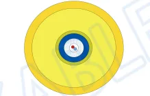
Dual-layer buoyant construction, 2SMF
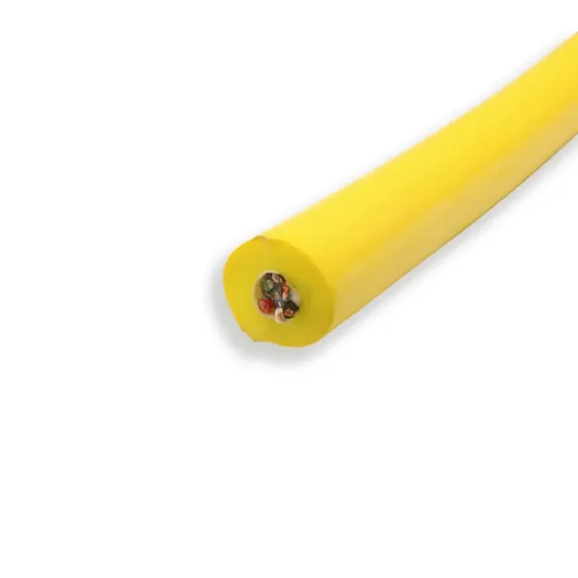
Zero-buoyancy two-fibre cable with LCP strength braid and dual-layer co-extruded TPU jacket, 6.5±0.3mm, for subsea observation and survey links.
Product overview
A zero-buoyancy cable is the key link between underwater equipment and the surface control unit in underwater survey, observation and work systems. Its weight in water is essentially balanced by buoyancy, so it neither floats up nor sinks; this reduces the restraint the cable imposes on the attitude of the underwater platform and the extra load on the propulsion system. This product uses a dual-layer co-extruded buoyant construction with single-mode fibre as the transmission medium, and suits subsea applications that need long-distance, high-bandwidth data return and are sensitive to cable weight.
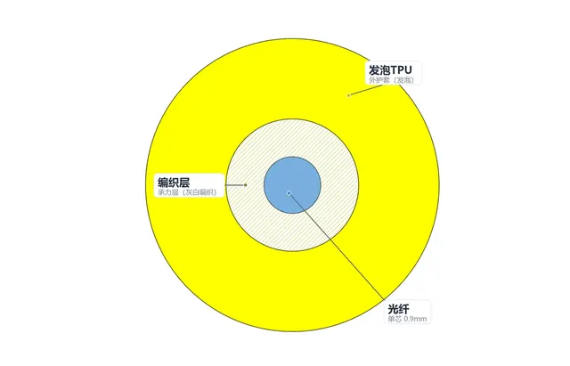
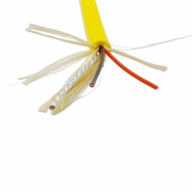
Unlike common power and fibre composite cables, this product has no copper power cores: the cable performs only three functions - optical signal transmission, load bearing and buoyancy. From the inside out the cross-section is fibre unit, strength braid, foamed inner jacket and gloss outer jacket, each layer with a distinct, non-interfering role: the fibre carries no tension, the strength layer carries no signal, the foam layer provides buoyancy only, and the outer jacket provides water blocking and abrasion resistance.
Construction and materials
- Fibre unit: two single-mode armoured fibres, blue coating, 2.0mm outer diameter
- Strength layer: LCP 1000D fibre, 8+8 braid, 16 carriers, coverage approximately 80%
- Inner jacket: foamed TPU, low-density layer providing buoyancy
- Outer jacket: TPU, gloss finish, yellow
- Finished outer diameter: 6.5±0.3mm
The fibre unit sits at the centre and the surrounding strength braid transfers pulling force from the core to the fibres, so the fibre never takes the load directly. LCP fibre has high specific strength and low water absorption; once braided it carries the longitudinal load and also forms a mechanical layer around the fibres inside. The braid is laid with surplus length, so the cable stays supple while retaining the necessary abrasion and crush resistance.
The inner jacket is foamed TPU: uniform cells introduced into the material lower the apparent density so that the net weight of the cable in water approaches zero. The thickness and expansion ratio of the foam layer together set the buoyancy; dual-layer co-extrusion forms the foam layer and the gloss outer layer in one operation, giving a tight bond between the layers that resists delamination. The outer jacket is gloss TPU with a smooth surface that reduces drag and makes cleaning and inspection after use easier; the yellow colour is easy to identify both in water and on deck.
Function of dual-layer co-extrusion
Dual-layer co-extrusion means the foamed inner layer and the solid outer layer are extruded simultaneously and applied over the core in one pass. Compared with the two-pass route of extruding the foam and then sheathing it, single-pass forming reduces trapped air between layers and repeated heating, gives a more stable interface bond and makes the outer diameter easier to control.
The foam layer must stay at low density to generate enough buoyancy, but a purely foamed surface has limited strength and would be damaged by handling and friction if used as the outermost layer. The gloss outer layer therefore takes on abrasion, tear and water-blocking duty while the inner layer provides buoyancy, each material doing its own job. This division also means that when the cable is repeatedly bent, the dense outer layer constrains the inner layer and reduces the risk of the foam being flattened, which would shift the buoyancy.
Key characteristics
- Neutral buoyancy: weight in water is close to balanced with buoyancy, so the cable is less likely to snag on underwater equipment during deployment and recovery
- Interference-free transmission: the signal is carried by fibre and is unaffected by electromagnetic interference
- Separate load-bearing and transmission: the strength member is arranged outside the fibre, so the fibre stays at low stress long term
- Supple and easy to handle: braided strength layer with foamed jacket gives a soft cable suited to winch and manual deployment
- Water and corrosion resistance: the jacket is thermoplastic polyurethane, which resists hydrolysis and mould growth in long-term immersion
- Easy identification: the yellow outer sheath is conspicuous in turbid water and on deck
Transmission and mechanical performance
Single-mode fibre has low attenuation and ample bandwidth over long distances and can carry video, sonar data and equipment control signals. The tensile capacity of the cable is governed mainly by the fibre specification and braid density of the strength layer, while bending behaviour depends on the softness of the foam layer and the jacket thickness. Figures for fibre attenuation, tensile strength, minimum bending radius and water pressure resistance are set out in the specification document confirmed by both parties and can be adjusted for different working depths and deployment methods.
Note that buoyancy depends on depth, water temperature and the water absorption of the jacket, so the same cable does not behave identically in fresh water and seawater. For projects with strict buoyancy balance requirements we recommend testing in the target water body, or allowing adjustment margin for weights and buoyancy blocks at the design stage.
Typical applications
The cable suits signal connections for underwater vehicles, subsea observation platforms, towed survey equipment and underwater camera systems. On equipment that hovers for long periods or cruises at low speed, neutral buoyancy markedly reduces the load on the thrusters; where the cable is deployed and recovered frequently, the supple construction resists kinking on the winch and is easy to handle manually.
For survey links that only need optical signal return and no power over the cable, the cable can be made lighter and thinner and takes up little space during deployment; in strong electromagnetic environments or waters with high lightning risk, fibre transmission is also less susceptible to coupled interference.
Selection and customisation notes
Three conditions should be established first: transmission distance and signal type, which determine fibre count and type; working depth and deployment method, which determine jacket thickness, strength layer configuration and finished outer diameter; and buoyancy requirement, which determines foam density and thickness. Once these are set, the construction can be adjusted per project.
Items that can be customised include fibre count and type, strength fibre specification and braid density, foam expansion ratio of the inner jacket, outer jacket colour and surface finish, finished outer diameter and delivery length. For special underwater equipment, branches or connectors can also be provided at either end. All specifications are subject to the specification document confirmed by both parties.
Our underwater and buoyant cable lines cover the complete cabling, braiding and dual-layer co-extrusion processes, and we can provide structural design and sample verification per project.
Related in Zero-Buoyancy Cables
Engineering enquiry