Double-Layer Neutrally Buoyant Cable 2×14AWG+24AWG+1SMF 200 kg
Zero-Buoyancy Cables · Marine & Subsea
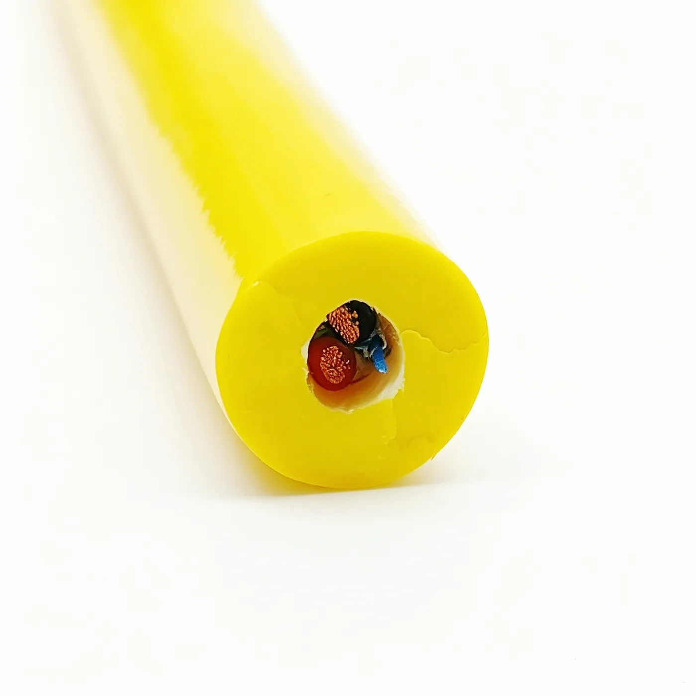
Double-layer neutrally buoyant cable 2×14AWG+24AWG+1SMF
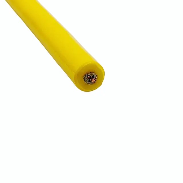
Double-sheath neutrally buoyant cable with 2×14AWG power, one 24AWG signal core and one single-mode fiber, LCP strength members, 200 kg, 14.8 mm.
Product overview
The double-layer neutrally buoyant cable is a subsea composite cable that integrates power supply, signal transmission and fiber communication in one cable body. Its design aim is to keep buoyancy close to neutral in water and to reduce the effect of the cable's own weight on equipment attitude and hovering stability. It suits the power, control and communication circuits of subsea vehicles, subsea inspection and subsea work equipment, and is particularly suitable for repeated launch and recovery, long hovering periods and greater working depth.
The cable has a two-layer construction. A foam layer is formed over the core to provide buoyancy and to cushion external loads; a solid sheath is then extruded over the foam to face water pressure, sand and gravel abrasion and impact and to protect the core. Independent strength members are laid in parallel in the core during cabling, so the tension generated by launch, recovery and towing is carried mainly by the strength members and the conductors and fiber are not loaded directly; copper strand breakage and increasing fiber attenuation during winch traction, underwater movement and repeated bending are therefore unlikely.
The buoyancy state of the cable can be adjusted to the application. During deployment, working depth, suspended length, current velocity and terminal load should be considered together so that the load and attitude of the cable in water remain stable. The construction described on this page is the typical practice for this specification; the final construction is subject to the specification document confirmed by both parties.
Construction and materials
- Conductor: stranded bare copper,
- Signal core conductor: 7/0.2 stranded construction
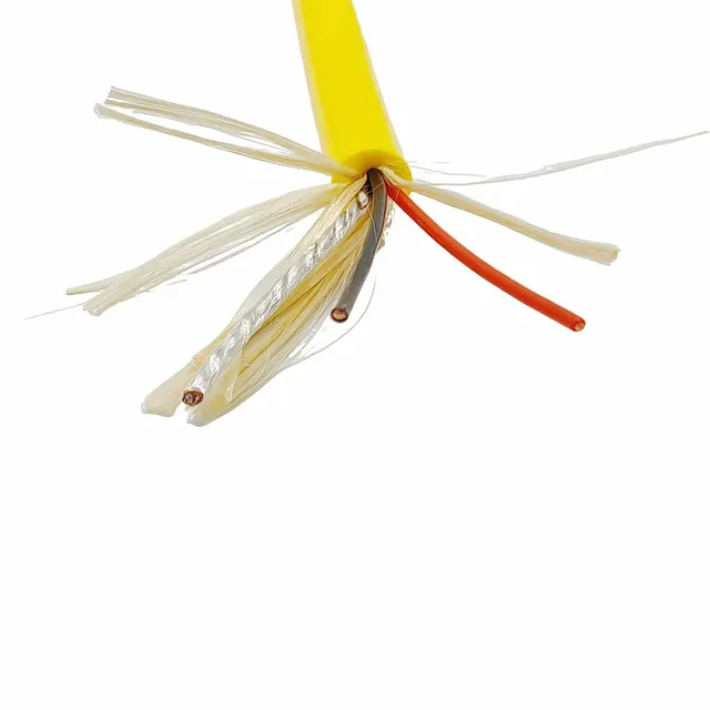
The two power cores are 14AWG with a conductor cross-section of 2.08 mm², stranded in a left-hand lay. The bare copper conductor gives stable conductivity, and the stranded construction keeps the cores flexible for small-radius coiling during repeated launch and recovery.
- Insulation: PE, 0.55 mm thick
The signal core is 24AWG, also stranded bare copper, and is cabled in the same core as the power cores for control signals or data return.
- Signal core insulation: PE, 0.2 mm thick
The power cores are extruded with polyethylene insulation of uniform thickness and a round surface, which aids the subsequent cabling and sheath extrusion processes.
- Fiber unit: one single-mode fiber
The power and signal cores are identified in red, black and green, which makes termination at both ends easy to identify and reduces the risk of miswiring on site.
- Strength member and fillers: 7 LCP fibers plus PP yarn
The fiber is cabled together with the core for long-distance data return. Bends tighter than the permitted bending radius should be avoided during installation and handling so that communication quality is not affected.
- Tape: non-woven tape wrapping
High-strength LCP fibers are laid in parallel as strength members during cabling, together with PP yarn fillers, so that the core section is round with small voids and the sheath does not sink in during extrusion.
- Foam layer: foam applied over the core
Non-woven tape is wrapped over the core for separation and shape retention, preventing the core from loosening or shifting during the subsequent extrusion process.
- Outer sheath: TPU, yellow
The thickness and degree of foaming directly affect the net buoyancy of the cable in water and the cable diameter, and must be designed together with the sheath thickness to obtain a stable buoyancy state.
The finished outer diameter after extrusion is 14.8±0.5 mm with a glossy sheath surface. The yellow sheath is highly visible underwater, which aids observation, identification and recovery.
Key features
- Neutral buoyancy: the net buoyancy of the cable in water is close to zero, which reduces its effect on the attitude and hovering position of the subsea platform and also lowers towing drag.
- Independent load path: strength members are arranged separately from the conductors, so launch, recovery and towing tension is not transmitted to the copper strands and fiber.
- Double-layer protection: the inner foam layer provides buoyancy and cushioning, while the outer solid sheath resists water pressure, abrasion and impact.
- Optoelectric composite: power and communication are laid in one cable, so a single deployment meets power, control and data transmission needs at the same time.
- Color identification: each core is clearly color-coded, which simplifies termination and fault finding on site.
- Adjustable construction: buoyancy state, core combination and end preparation can be redesigned per project.
Electrical and mechanical performance
- Rated voltage: confirmed to project requirements, subject to the specification document confirmed by both parties.
- Electrical insulation: polyethylene insulation combined with a round core construction, suitable for long-term subsea installation.
- Tensile strength: overall tensile strength designed at 200 kg; the load is carried by the strength members and the conductors and fiber do not take the main tensile load.
- Bending performance: suitable for winch launch and recovery and underwater movement; the minimum bending radius depends on the actual installation method and end fixing.
- Fiber transmission: the single-mode fiber is deployed with the cable and does not affect communication quality within the permitted bending radius.
- Environmental resistance: the outer sheath is thermoplastic polyurethane, resistant to water, abrasion and tearing, and suitable for long-term use in subsea and wet environments.
Typical applications
- Subsea vehicles and submersibles: power for thrusters, lighting, pan-tilt units and sensors, with control signals and video data returned over the same cable.
- Subsea camera and observation systems: during long hovering periods the cable weight does not noticeably pull on the equipment, giving steadier images.
- Subsea inspection and sampling equipment: the optoelectric construction returns survey data to the surface in real time.
- Tanks, lakes and coastal testing: short lengths for repeated launch, recovery and tow tests to observe buoyancy and flexibility.
- Subsea work and maintenance tools: where power and control signals must be transmitted together.
Selection and customization
- We recommend providing working depth, suspended length, required buoyancy state, tensile requirement and the interface type at both ends so that cable diameter, strength construction and sheath thickness can be determined.
- The medium (fresh water or seawater), ambient temperature and handling method affect the choice of sheath material and surface finish; please state these at selection.
- If different core counts, cross-section combinations or fiber counts are required, the conductor construction and cabling process can be redesigned per project.
- Length, end preparation and marking can be defined per project; specific parameters are subject to the specification document confirmed by both parties.
PAIDE Cable can provide construction recommendations and selection guidance based on the operating conditions; for other specifications, please contact our technical team.
Related in Zero-Buoyancy Cables
Engineering enquiry