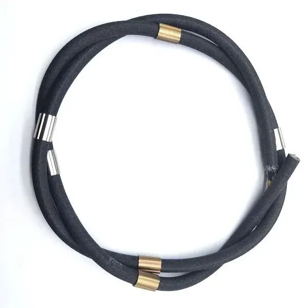
PDK71300-14x24AWG+STP CAT6-200KG Inclinometer Signal and Power Cable - 5000 N, 11.6 mm
Specialty & Instrumentation Cables · Industrial Automation
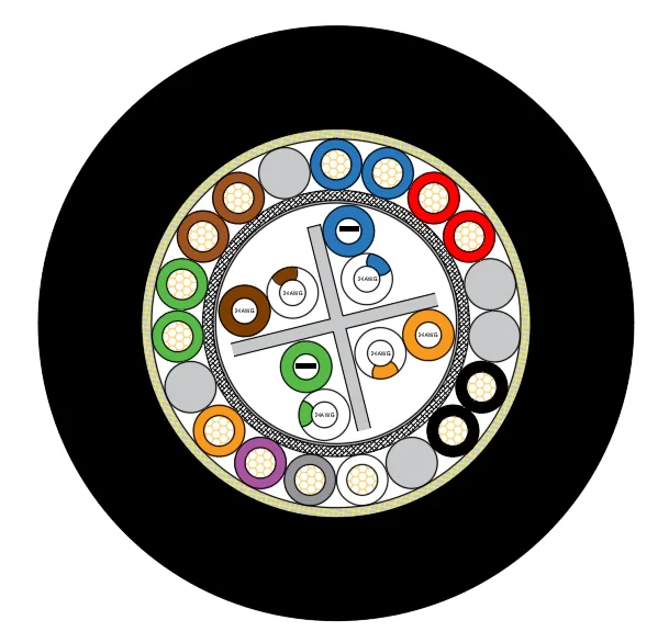
PDK71300
Inclinometer composite cable with 14x24AWG cores plus a shielded CAT6 unit, polyurethane sheath, 5000 N tensile strength and 11.6 mm outer diameter.
Product overview
Inclinometer cables carry signals and supply power to inclinometers, pipeline robots and related downhole instruments, usually in conditions of limited space, frequent bending, permanent damp, and dragging or suspended loads. For these conditions PAIDE Cable offers the PDK71300 and PDK71301 series of slim multi-core composite cables, which can combine power cores, signal cores, twisted pairs, coaxial video lines and network units in one cable to match the instrument interface, reducing the number of downhole connection points and making handling and maintenance easier on site.
In the specifications of this series that include a shielded network unit, the cable contains several power and signal cores as well as a shielded twisted-pair network unit, so that power supply and data return are both handled by one cable; where the instrument needs a coaxial video channel or larger power cores, the PDK71301 series offers a combination in which an aramid fiber tensile layer is provided in addition to the coaxial and control units. Both approaches aim to reduce downhole connection points and simplify handling on site.
Construction and materials
The specifications covered here are PDK71300-14x24AWG+STP CAT6-200KG, PDK71300-14x24AWG+3x2x24AWG-200KG, PDK71300-2x22AWG+STP CAT6, PDK71300-2x19AWG+2x2x26AWG-250KG and PDK71301-4x0.75+75-3+8x0.15-200KG; their construction and materials are as follows.
For the conductors, the power and signal cores are bare copper with a nominal cross-section of 0.2 mm2, a multi-strand construction and a stranded diameter of 0.61 ±0.04 mm, and the shielded twisted-pair network unit in the same model has the same cross-section and stranded diameter. For specifications requiring corrosion resistance or a long service life, tinned copper conductors can be used instead; in the two-unit specification both units use tinned copper, the thicker unit stranded from 34 wires of 0.15 mm with a stranded diameter of 1.0 mm and the thinner unit stranded from 19 wires of 0.1 mm with a stranded diameter of 0.5 mm. The coaxial composite specification places a coaxial unit and 0.15 mm2 control cores alongside the larger power cores, with the cabling construction combining power, video and control channels in one cable.
The insulation is polyethylene. The power and signal cores have an average insulation thickness of 0.2 mm, a minimum of 0.17 mm and an insulation diameter of 1.0 ±0.03 mm; the insulation diameter of the larger cores is correspondingly greater, with the larger power cores at 1.3 ±0.03 mm insulation diameter, 0.28 mm average and 0.23 mm minimum insulation thickness. Cores are distinguished by red, blue, brown, green, orange, purple, grey, white and black insulation for identification and connection at both ends.
For shielding and braiding, the network or signal unit in the composite cable can use an aluminium foil plus tinned copper braid composite shield to suppress external electromagnetic interference; some specifications add a braid over the cable core, for example the specification with the integrated shielded network unit uses 16 pcs 3000D LCP braiding. The shield type and braid coverage can be determined by the interference level on site and the flexibility requirement.
For filling and tensile strength, the spaces between cores are filled with polyethylene rods, cotton yarn or other materials so that the cabled construction is round and loads are evenly distributed. Inclinometer cables with higher load requirements have an aramid fiber braided tensile layer in the core or under the sheath, with the tensile class given by the kilogram value in the model suffix; the coaxial composite specification uses cotton yarn or polyester yarn together with aramid fiber and fillers, carrying the load while keeping the core round.
The outer sheath material is polyether polyurethane, which balances abrasion resistance and flexibility and is the usual choice for inclinometer cables. Sheath color can follow on-site identification practice, commonly orange and black. The specification with one integrated shielded network unit has a black sheath with an average thickness of 2.0 mm, a minimum of 1.7 mm and a finished outer diameter of 11.6 ±0.3 mm; the specification with three shielded twisted network pairs has an average sheath thickness of 2.5 mm, a minimum of 2.1 mm and a finished outer diameter of 11 ±0.3 mm; the coaxial composite specification has an average sheath thickness of 1.5 ±0.3 mm, a minimum of 1.3 mm and a finished outer diameter of 11.4 ±1.0 mm; two further slim specifications have finished outer diameters of 8.5 ±0.3 mm and 6.4 ±0.2 mm.
Key features
- Flexible combination: power, signal, twisted pairs, a coaxial unit and a network unit can be combined in one cable, matched to the instrument interface in one go and reducing downhole connection points.
- Separate strength member: the aramid fiber braided tensile layer sits in the core or under the sheath and takes the suspended load during installation, so the sheath and cores carry no direct weight.
- Oil and abrasion resistance: the polyether polyurethane sheath balances abrasion resistance and flexibility and suits damp downhole conditions with repeated handling and dragging.
- Good bending performance: the slim specifications accept small bending radii, which eases installation in confined spaces and where the cable is moved frequently.
- Selectable temperature and voltage: several rated voltage and temperature combinations are available for selection to the actual downhole temperature and supply conditions.
- Customizable construction: core count, cross-section, shield type, sheath material and tensile class can all be determined to project requirements.
Electrical and mechanical performance
For rated voltage, most specifications are 300/500 V, and the specification with three shielded twisted network pairs is 300 V; rated temperature covers the ranges -40 C to +90 C, -40 C to +105 C and -35 C to +105 C, so the cable can be selected for the actual downhole temperature.
For bending performance, the slim specifications allow smaller bending radii. The specification with one integrated shielded network unit has a minimum bending radius of 7 times the cable outer diameter in mobile installation; the same specification in fixed installation, the specification with larger power cores and the coaxial composite specification are all 10 times the outer diameter; the two-unit tinned copper specification is 15 times the outer diameter. During installation and use the cable should not be kept below its minimum bending radius for long periods, and concentrated load points on the sheath should be avoided.
For tensile strength and weight, the specification with one integrated shielded network unit has a tensile strength of 5000 N and a weight of about 153 g/m; the specification with three shielded twisted network pairs has the same tensile class and a weight of about 147 g/m. The higher tensile classes are achieved with an aramid fiber tensile layer; the tensile rating is related to cable weight and downhole depth, and the suspended length should be taken into account when selecting.
For electrical performance, the maximum conductor DC resistance at 20 C increases as the cross-section decreases: about 84.1 Ω/km for 0.22 mm2 and smaller, about 55.2 Ω/km for 0.34 mm2 and not more than 26 Ω/km for 0.75 mm2, while the thicker unit of the two-unit tinned copper specification is about 28.3 Ω/km. Models with a shielded twisted network unit have a characteristic impedance of 100 ±10 Ω.
Specification comparison
The specifications differ mainly in the combination of finished outer diameter, rated voltage, rated temperature and minimum bending radius: specifications with fewer cores and smaller cross-sections have a smaller diameter and a smaller permitted bending radius; specifications with several network units or a coaxial unit have a larger diameter because of the additional units; specifications with larger power cores or the two-unit construction trade a slightly larger diameter for a higher tensile class. When selecting, first determine the construction from the number of power and signal channels, then check the voltage class, temperature range and bending radius against the installation method and downhole temperature. These parameters are set out in the Construction and materials and Electrical and mechanical performance sections above, and actual supply parameters are subject to the drawing confirmed by both parties.
Typical applications
- Signal transmission and power supply for inclinometers and downhole instruments
- Composite wiring for pipeline robots, pipeline inspection equipment and manipulators
- Applications that must carry coaxial video, twisted-pair signals and power in one cable
- Working environments with frequent movement, repeated handling or dragging
Installation and handling notes
During handling and coiling, keep a sufficiently large bending radius and avoid hard kinks at the edge of reels, at the wellhead or elsewhere that would bend the cable beyond its design range. The load-bearing element is the aramid fiber braid in the core, so installation should use clamps matched to the tensile class; the sheath or cores should not carry the weight directly, and the cable should not be pressed repeatedly at the same point. Downhole humidity is high, so the ends should be reliably sealed and made watertight to prevent moisture from penetrating the insulation along the gaps in the core. Where the cable is moved and handled frequently, check the sheath and braid regularly for wear, fraying or broken wires and deal with damage promptly, to reduce the risk of signal interruption and insulation faults. When connecting a multi-core composite cable, check each core by insulation color to avoid mixing power and signal cores, and at the shielded end prepare the shield as required by the on-site earthing practice, so that interference current is led to earth instead of entering the signal circuit.
Customization and selection notes
The core count, cross-section, shield type, sheath material and tensile class of an inclinometer cable can be customized to the instrument interface and operating conditions, and power, signal, twisted pairs, a coaxial unit and a network unit can be combined in one cable. When selecting, please state the operating temperature range, whether installation is mobile or fixed, the minimum bending radius, the required tensile capacity and the signal transmission distance, so that a suitable outer diameter and construction can be determined. For parameters that cannot yet be fixed, please provide the operating conditions and the instrument interface, and PAIDE Cable will confirm the drawing before arranging production.
Related in Specialty & Instrumentation Cables
 Custom
 Inclinometer cable 4x0.5mm2
 Inclinometer cable 4×0.34 mm²
 On request
Engineering enquiry