Watertight Optoelectric Subsea Cable 4x2x20AWG, TPU Double Sheath
Watertight Optoelectric Cables · Marine & Subsea
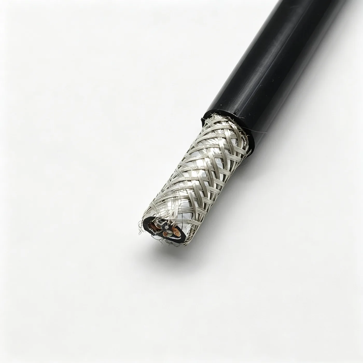
Subsea cable 4x2x20AWG
Watertight optoelectric subsea cable with four 20AWG pairs, tinned copper conductors, double braid plus foil shield and TPU double sheath, 12.9 mm OD.
Product overview
This product is the subsea cable of the PAIDE watertight optoelectric cable range. It uses a four-pair, two-core construction (8 cores in total), with conductors and shields designed for long-term submersion. Tinned copper strands serve as the conducting and drain elements throughout; the pairs are insulated, shielded with a double braid plus aluminum foil composite, and the outermost layer is a black TPU sheath applied by extrusion.
The construction aims to put power and signal transmission into one cable and to solve three problems: no voids are left inside the core, which reduces the chance of water penetrating longitudinally; the shield is continuous, which suppresses interference from motors, VFDs and other sources on the signal pairs; and the sheath resists oil, abrasion and hydrolysis for both towing and long-term immersion. Power pairs and signal pairs are arranged in sequence in the same core, with the lays staggered pair to pair and filling and wrapping applied so that the core is round and clearly layered.
A subsea cable sees different loads from a land cable: when towed, the body takes tensile load and repeated bending; in fixed installation it withstands water pressure and temperature change over the long term. This product therefore places tape separators between layers and separates shield from sheath, so that if the outer layer is damaged the inner layers still maintain basic insulation and signal paths, which simplifies later repair.
Construction and materials
- Conductor: tinned copper strands, left-hand lay, conductor diameter after stranding 0.91 mm. The tin coating slows oxidation of the copper in damp conditions and eases soldering and termination.
- Insulation: PE, core diameter 1.6 ±0.01 mm. The four pairs are matched green/white, blue/white, orange/white and brown/white, then twisted with lays of 32 ±0.2 mm, 42 ±0.2 mm, 40 ±0.2 mm and 50 ±0.2 mm respectively, staggered pair to pair to reduce crosstalk.
- Cabling: the four pairs are arranged in sequence and cabled left-hand, cabled core diameter 7.9 ±0.3 mm; the interstices are filled solid with transparent PP yarn and wrapped with polyester tape; a 19/0.15 tinned copper drain wire is cabled in at the same time to discharge induced currents from the shield.
- Double shielding: both the inner and outer layers use 10/0.1 tinned copper wire, 16-carrier braid, 80% coverage. After the inner braid, aluminum foil is applied with the conductive side facing inward; outside the inner sheath a further aluminum foil is applied with the conductive side facing outward, giving a composite braid-and-foil shield.
- Inner sheath: TPU, black, extruded 0.8 mm thick, inner sheath diameter 9.5 ±0.3 mm.
- Outer sheath: TPU, black, extruded 1.5 mm thick, finished diameter 12.9 ±0.3 mm. After the outer braid a polyester tape is applied before the outer sheath is extruded, so the braid is not disturbed or displaced during extrusion.
Layers are separated by tapes, and the lay directions and cabling structure work together; from inside out the cable is conductor, insulated pairs, filler and drain wire, inner shield, inner sheath, outer shield and outer sheath - clearly layered and easy to strip and terminate.
Key features
- Dense core: filler yarn fills the interstices and the tapes are tightly wrapped, while both sheaths are extruded, so there are few voids inside the core and little chance of a continuous longitudinal water path.
- Composite shield: the tinned copper braid provides a low-resistance shield path, the foil covers the braid gaps, and induced currents are discharged through the drain wire.
- Tight sheath: both sheaths are TPU and bond to the layers beneath after extrusion; they resist oil, abrasion and hydrolysis and suit subsea towing and fixed installation.
- Corrosion-resistant conductor: tinned copper is more stable than bare copper in long-term damp conditions and does not blacken before termination.
- Power and signal in one cable: both types of pair share one cable with staggered lays, saving wiring cost and installation space.
Electrical and mechanical performance
- Conductor DC resistance, insulation resistance and withstand voltage are provided as measured data once the specification is confirmed for the project.
- Rated voltage, operating temperature range and finished weight vary with the construction and can be customized to the project.
- Minimum bending radius is determined by the finished outer diameter and the installation method; fixed and mobile use take different values.
- Tensile and load-bearing requirements can be met by adjusting the conductor construction or adding strength members.
Electrical parameters not listed above are subject to the specification file confirmed by both parties; no values are stated as assumptions.
Typical applications
- Power and signal transmission for ROVs and subsea work tools.
- Connecting cables for subsea observation equipment, sensor arrays, cameras and lighting.
- Mobile or fixed installation in offshore engineering, water conservancy and hydropower projects and subsea inspection equipment.
- Power and signal composite connections in test tanks and flumes under long-term immersion.
- Wet-end equipment that must carry power together with network and control signals in one cable.
Selection and customization notes
Selection requires the working depth and installation method (towing or fixed), the number of pairs and conductor cross-section, voltage class and permitted voltage drop, signal type and shielding requirements, ambient temperature and sheath color.
- Pair count, conductor cross-section and shielding method can be adjusted to the project; power pairs can share the cable with network and control pairs.
- Sheath color and supply length are made to project requirements, subject to the specification file confirmed by both parties.
- If lifting forces are high or weight must be reduced, strength members can be added or the sheath wall thickness adjusted.
- Termination, connectors and accessories can be supplied with the cable and confirmed to project needs.
Related in Watertight Optoelectric Cables
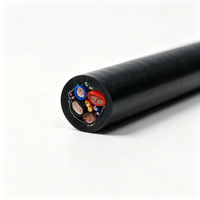 4×2×24AWG (UTP) + 2×14AWG + 2×12AWG
 Custom
 Longitudinally watertight cable 2×22AWG+STPCAT6-100KG
 PDK81301
Engineering enquiry