2×22AWG + STP CAT6 100 kg Longitudinally Watertight Optoelectric Cable, 8.4 mm
Watertight Optoelectric Cables · Marine & Subsea
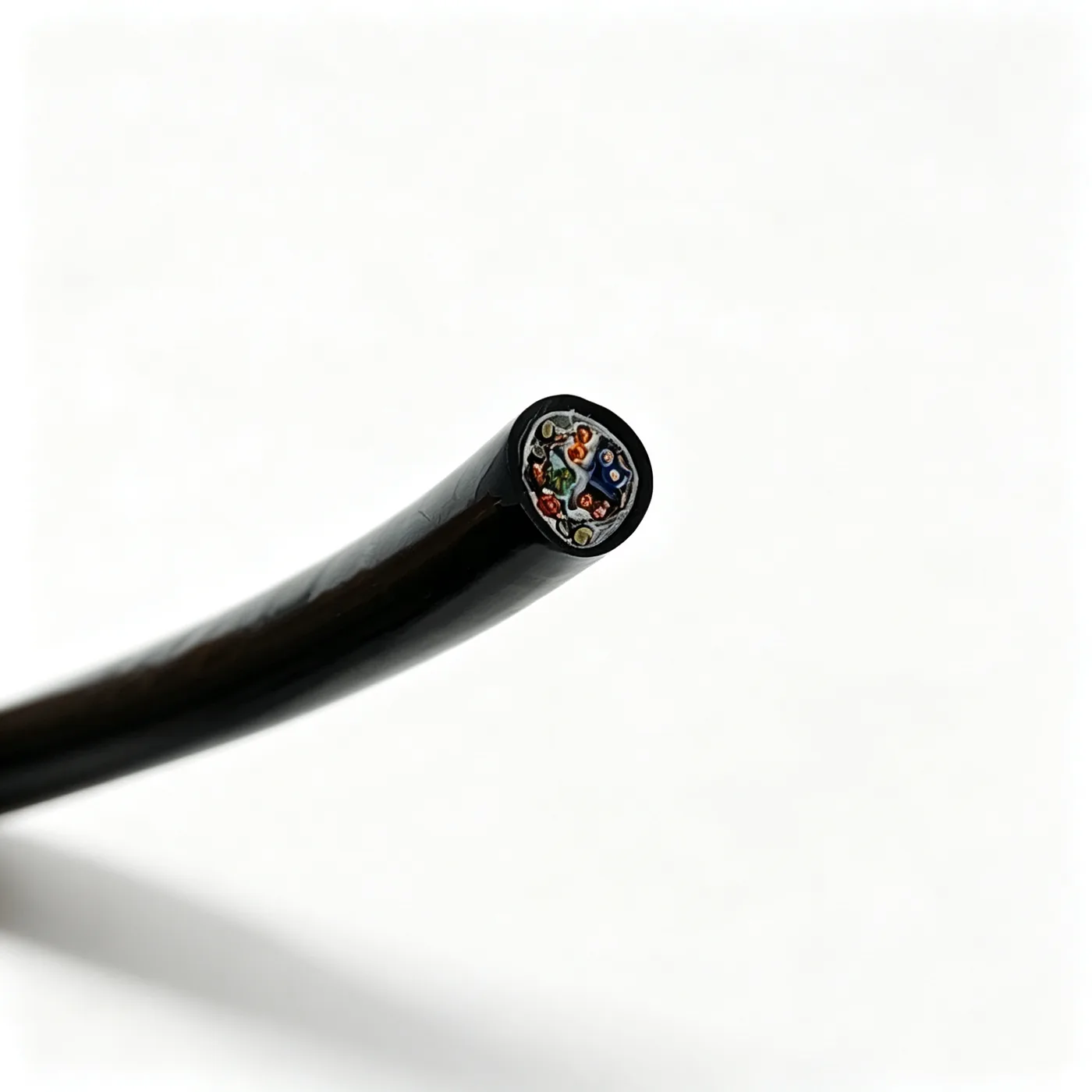
Longitudinally watertight cable 2×22AWG+STPCAT6-100KG
Longitudinally water-blocked composite cable with 2×22AWG power cores and one shielded CAT6 unit, LCP strength yarn and TPU sheath, 8.4 mm OD.
Product overview
The longitudinally watertight cable 2×22AWG+STPCAT6-100KG is a special cable of longitudinally water-blocked composite construction, combining two power cores and one shielded Category 6 (CAT6) twisted-pair data unit in a single cable body, so that power supply and network data return for underwater equipment run over one cable. This reduces penetrations, bulkhead openings and harness count, and eases the mating of underwater connectors and watertight feedthroughs.
The core is designed on the principle of longitudinal water-blocking: the voids between units are filled with water-blocking compound and filler strips, and the outside is wrapped with polyester tape and non-woven tape, so that seawater or condensation finds it difficult to seep longitudinally inside the core. This suits conditions requiring long-term immersion, frequent immersion or repeated temperature cycling.
The cable carries both the power circuit and the shielded data circuit, with insulation, shielding and load-bearing structures arranged independently: the current-carrying needs and flexibility of the power cores are met, while the pairing and shielding of the data unit remain intact so that the power circuit does not interfere with the data signal.
Construction and materials
- Conductor: stranded bare copper wire (power core, cross-section approximately 0.34 mm²)
- Data conductor: stranded bare copper wire
- Insulation: PE, 0.3 mm thick (power core insulation diameter 1.3 mm)
- Data core insulation: PE, 0.22 mm thick
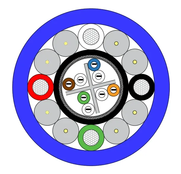
- Data unit construction: four twisted pairs with a cross filler, water-blocking compound and aluminium foil inside, and a tinned copper wire braid shield outside with coverage of approximately 80%
- Strength member: LCP 3000D yarn embedded in the PE filler strips and laid with the cable, with the voids between cores filled with water-blocking compound
- Inner wrap: polyester tape plus two layers of non-woven tape
- Outer sheath: TPU, 1.0 mm thick, black, extruded
- Cabling diameter: 6.6±0.2 mm; finished outer diameter: 8.4±0.3 mm
The power cores use finely stranded copper wires with a lay direction matched to the cabling direction, so that the cable does not open up under repeated spooling; the twisted pairs of the data unit combined with aluminium foil and tinned copper braid form a continuous shield, over which polyester tape and then non-woven tape are applied, both to prevent the shield from being stretched when the sheath is extruded and to provide a degree of cushioning and thermal insulation.
The sheath is black TPU, extruded tightly over the non-woven inner wrap so that no continuous gap remains between core and sheath; the material itself resists hydrolysis and oil, has a dense surface and absorbs little water, making it suitable for long-term use underwater or in damp environments.
Key characteristics
- Longitudinal water-blocking: voids between cores are filled with water-blocking compound and filler strips, largely blocking the seepage path for water pressure along the cable.
- Power and data in one cable: two power cores supply the equipment and the shielded Category 6 data unit carries network data return, meeting both needs in one installation.
- Complete shielding: twisted pairs, aluminium foil and tinned copper braid work together in the data unit to suppress external electromagnetic interference and to reduce crosstalk from the power circuit into the data signal.
- Independent strength member: the strength yarns do not conduct; during pulling, spooling and repeated bending the load is carried mainly by the strength structure, so the power cores and data unit are not directly loaded.
- Hydrolysis and oil resistance: the TPU outer sheath tolerates seawater, oil and common chemical media well, and its dense surface absorbs little water.
- Flexible and easy to install: the cabling structure and filler units work together to keep the cable supple, allowing routing, deployment and conduit work in confined spaces.
Electrical and mechanical performance
After cabling, the cable is checked for continuity and insulation, with the power and data circuits verified separately to confirm that stranding, shielding and sheathing have not damaged the cores; finished cables are delivered after the pre-delivery tests required by the project.
- Rated voltage: subject to the specification document confirmed by both parties.
- Temperature range: subject to the specification document confirmed by both parties.
- Minimum bending radius: subject to the specification document confirmed by both parties.
- Tensile load-bearing: strength members are configured to the load rating marked on the model; specific values are subject to the specification document confirmed by both parties.
- Electrical consistency: power cores and data unit are tested separately in the finished state, and shield continuity is checked separately.
Because voltage class, installation method and load-bearing requirements differ considerably between projects, the figures above should not be applied directly; selection is subject to the specification document confirmed by both parties, and values can also be verified by measurement at the sample stage.
Typical applications
- Combined power and data transmission lines for underwater robots and underwater work equipment.
- Power and control wiring for underwater camera, lighting and pan-tilt units.
- Signal return for underwater sensors, sonar and monitoring arrays.
- Underwater extensions of shipborne, buoy and offshore platform equipment.
- Wiring for immersion conditions in tanks, test facilities and inspection equipment.
- Monitoring lines in permanently immersed environments such as marine ranching and water conservancy gate control.
In these applications the cable usually faces bending, spooling, water pressure and oil at the same time; the composite construction reduces the mating points created by laying separate power and network cables and lowers the probability of underwater failure.
Selection and customisation notes
- Core count, cross-section and data unit category can be combined to project requirements, and the ratio of power to data circuits can be adjusted within the same construction.
- Shield type, sheath material and colour, load rating, reel length and end termination are all open to discussion.
- For long-term immersion or repeated spooling, the load rating, installation method and deployment conditions should be defined at the selection stage so that the construction can be finalised in one step.
- Construction and dimensions are subject to the specification document confirmed by both parties; samples and drawings can be confirmed first, followed by volume production.
Related in Watertight Optoelectric Cables
Engineering enquiry