Single-Layer Neutrally Buoyant Cable 4x2x26AWG, Foamed TPU Sheath, 7.8 mm
Zero-Buoyancy Cables · Marine & Subsea
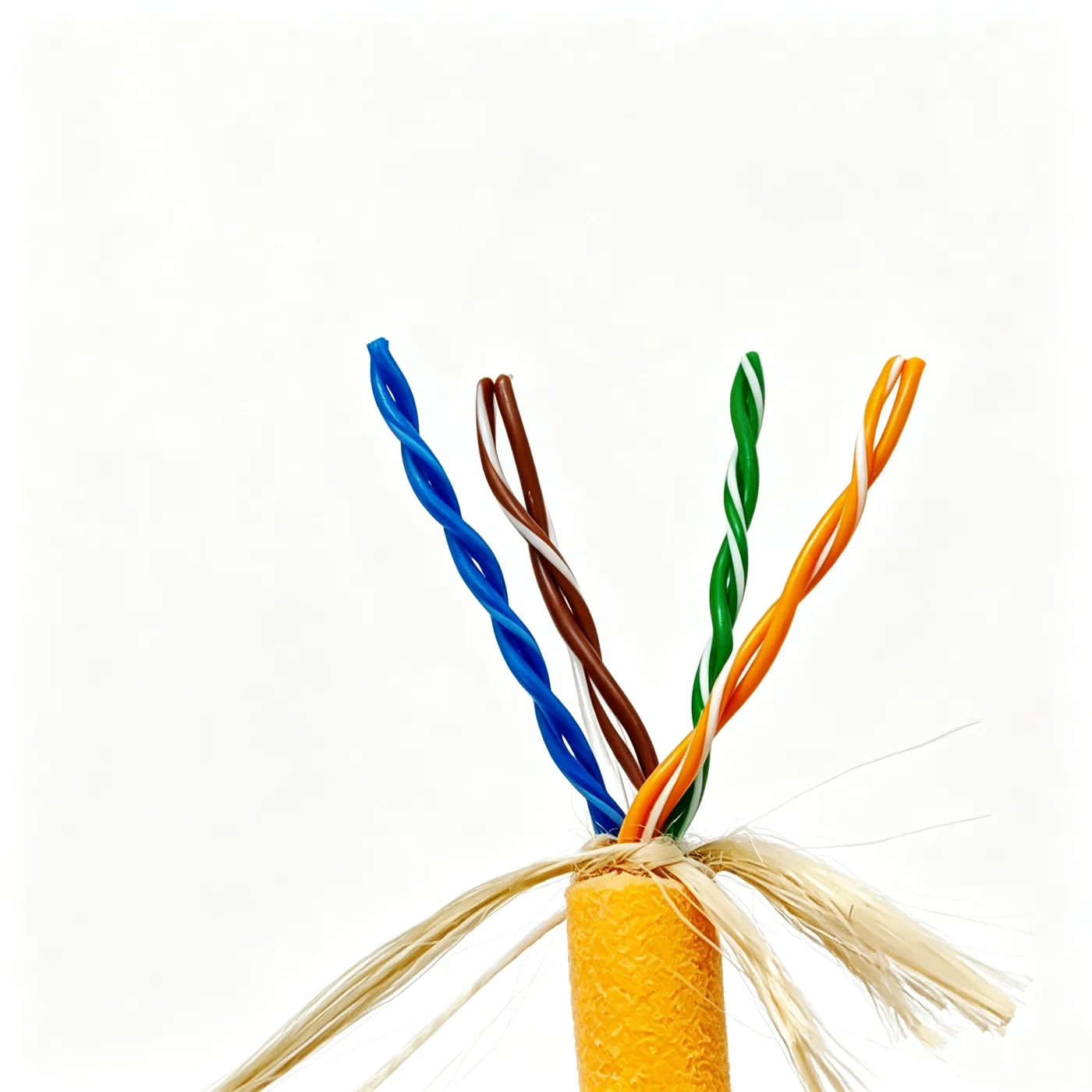
Single-layer buoyant cable 4x2x26AWG
Single-layer neutrally buoyant cable, four 26AWG pairs, bare copper, 0.25 mm PE insulation, LCP strength yarns, foamed TPU sheath, 7.8 mm OD.
Product overview and use
The single-layer buoyant cable is used for signal transmission to underwater equipment. Four signal pairs are cabled together and covered with an extruded foamed outer sheath, so that the cable density approaches that of water and the cable floats when submerged, adding no extra drag to the descending equipment during deployment and recovery. The cable is supple and compact in diameter, making it suitable for repeated coiling in confined waters and inside equipment housings.
The outer layer is a single-sheath construction, which gives a smaller diameter and lower weight than a double-sheath design, making it suitable for small underwater platforms where volume and weight are critical. The four pairs are twisted individually and then cabled together, suppressing electromagnetic coupling between pairs; a single cable can carry multiple signal channels and sensor returns, reducing the number of underwater penetration harnesses and connectors.
The product is suitable for control signals and data return of underwater cameras and lighting, control loops of small thrusters, and data return from attitude and pressure sensors. It is also used for instrument wiring on water quality monitoring buoys, ocean observation platforms and towed underwater survey bodies. It can be configured for project use in inland river, coastal and deep-water operating environments.
Construction and materials
Conductor: bare copper strands,
Insulation: PE, insulation outer diameter 1 mm, insulation thickness 0.25 mm
Filler and strength member: 4 LCP fibre yarns (3000D) + 2 water-blocking yarns
Wrapping: non-woven fabric
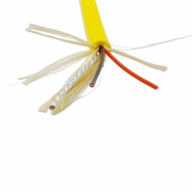
Outer sheath: foamed TPU, thickness 1.75 mm, orange
The product type and specification are single-layer buoyant cable 4x2x26AWG. The conductor is formed from multiple fine copper strands twisted into a bundle, with the stranding direction coordinated with the subsequent cabling direction so that the cable does not loosen under load or kink when bent. Polyethylene is used for insulation, with insulation thickness and diameter selected according to the overall pair dimensions; a uniform insulation diameter facilitates pair twisting and overall cabling. Pairs are colour-coded green/green-white, blue/blue-white, orange/orange-white and brown/brown-white in four groups for polarity identification at both ends.
The cabling operation twists all elements in the same direction to a cabled diameter of 4.3 mm, with a tight and round lay. Four LCP fibre yarns and two water-blocking yarns are placed in the centre: the former act as strength members carrying tensile loads during installation and recovery, while the latter swell on contact with water if the sheath is slightly damaged, blocking longitudinal water paths. A non-woven tape is wrapped over the core to fix the positions of the pairs, cushion sheath compression and provide separation.
This construction contains no braided shield; the cable prioritises suppleness and low weight. The outer sheath has a foamed structure that reduces material density to generate buoyancy while retaining a dense, abrasion-resistant outer surface. The sheath is applied in a single extrusion over the core; the finished outer diameter is 7.8 ± 0.2 mm, and the surface is round and smooth for passage through fairleads and winch sheaves.
Key features
Buoyancy is provided by the foamed sheath: cable density approaches that of water, so the cable stays suspended underwater instead of sagging or dragging on the bottom under its own weight, which reduces demands on propulsion and attitude control when used with underwater equipment.
Separating the load path from the signal path is the key point of this construction. Tensile load is carried by the central fibre yarns, so the pairs carry almost no longitudinal tension and the conductors are not thinned or broken during deployment, recovery and towing.
The foamed outer sheath resists water, oil and common chemical media, and its dense surface layer is abrasion and tear resistant, making it suitable for long-term use in sandy and saline environments.
The non-woven wrapping stabilises the cabled structure and keeps the pairs in fixed relative positions, so they do not shift and rub against each other during deployment, which helps maintain stable electrical parameters.
The overall construction is supple and can be coiled repeatedly at a relatively small bend radius, meeting the routing needs of winch drums and confined spaces inside equipment. Clear pair colour grouping makes identification easy during field assembly and servicing.
Electrical and mechanical performance
The electrical performance of the signal channels is directly related to conductor stranding quality and insulation concentricity. The stranded construction gives a more uniform electric field distribution at the conductor surface, and with the pairs fixed in position after cabling, transmission impedance and loop loss are more stable. Crosstalk between the multiple pairs in one cable is controlled by stranding direction and cabling layout, allowing several control and acquisition signals to be transmitted in parallel within a single cable.
The insulation material maintains stable dielectric performance and insulation resistance under long-term immersion, while the sheath provides mechanical protection and watertight sealing. Mechanically, tensile capability is determined mainly by the built-in strength fibre yarns, and the strength grade can be adjusted to project requirements; the sheath provides abrasion, tear and hydrolysis resistance. Rated voltage is not stated in this specification and can be defined per project, subject to the specification document confirmed by both parties. Where stricter electrical requirements apply, the insulation construction can be adjusted or a shield added at the design stage.
Typical applications
- Control signals and data return for underwater pan-tilt heads and cameras
- Control loops and status feedback for small underwater thrusters
- Control lines for underwater light units, strobes and other peripheral equipment
- Signal harnesses for attitude, pressure and temperature sensors
- Instrument wiring for water quality monitoring buoys and ocean observation platforms
- Signal connections for towed underwater survey bodies and sampling equipment
These applications share sensitivity to equipment weight, frequent deployment and recovery, several parallel signal channels and limited routing space, where the single-layer buoyant construction offers clear advantages in diameter and weight. Where higher load capacity or greater operating depth is required, additional sheath layers or a different strength member configuration can be added.
Selection and customisation notes
First clarify the application and installation method. If signal transmission dominates and deployment is frequent, this construction is the preferred choice; if the same cable must carry a larger current, the conductor cross-section and sheath thickness need separate calculation to avoid sheath degradation from cable heating.
Second, confirm the environmental conditions. For long-term immersion, focus on the hydrolysis resistance of the sheath and on the water-blocking arrangement; for coastal and sandy waters, focus on the abrasion and tear resistance of the outer sheath; for cold water, assess the low-temperature bending behaviour of the materials.
Third, confirm the interface and termination method. Pair grouping, colour identification, shielding requirements and termination process should be agreed in advance; if necessary, the breakout length and end treatment can be adjusted.
Fourth, confirm the length and coiling method. Delivered length, reel type and per-reel breaking points affect the installation plan and the number of field splice points, and should be determined from actual site conditions.
The construction, materials and performance described above can all be adapted per project, for example pair count, strength member specification, sheath colour and sheath construction, subject to the specification document confirmed by both parties.
Related in Zero-Buoyancy Cables
Engineering enquiry